I was able to get BASIC running with out much difficulty once I overcame a bit of confusion with the compiler I was using. First, I started with Z80 Basic by Grant Searle. The only file that needed to be altered was intmini,asm. I made some minor changes to use the TL16C550 UART at 115,200 baud. To get things going quickly, I removed most of the error checking which had more to do with buffer over-runs. I figured, at 115K and my slow typing, I didn't really need them.
As I mentioned, my compiler threw me for a loop. There was a configuration setting I missed that would offset the compiler output by 0x100. The code compiled fine and some of the basic functions worked but the UART interrupt didn't work. Due to the setting in the compiler, all the interrupt vectors were NOP'd and offset by 0x100. The UART would generate the interrupt but, since the vector was a NOP, it would run until 0x100 where the reset vector ended up. It took me longer to figure this one out than it should have..........but I did and BASIC is now running.
Wednesday, November 15, 2017
Tuesday, August 29, 2017
Added a UART to the Z80
I added a UART to the Z80 board. The original thought was to use a PIC on a separate board to do the UART function but the PIC wasn't quite fast enough. I ended up using a TL16C550 from Texas Instruments and along with a Microchip MCP2200 UART to USB chip. I've used the MCP2200 many times before as finding a 9 pin RS232 COM port on a PC is getting hard these days. I've been able to get UART input and output at 115.2KBaud with no issues.
Z80 CPU with UART Schematic
Friday, August 25, 2017
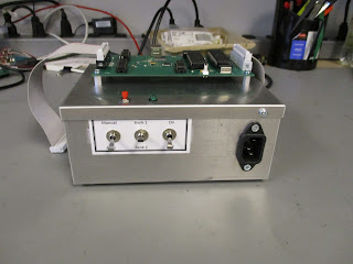
Programmer Version 2 now in a box
I made a modification to the programmer board and finally
got around to building and testing it. All I did was add a 128Kx8 SPI EPROM for
program storage. The original programmer worked fine but the Z80 board, since
it has no ROM, had to have a program loaded each time it was turned on. With
the EPROM on board, depending on the configuration switches, the Z80 will start
up as before (Manual mode), or automatically load a RAM image and start
running. There is a second switch to indicate which of the 2 images to load. I
also ended up putting it into a box with a 5V power supply to make it a bit
easier to work with when away from the lab. The Z80 board is mounted on top
with the programmer mounted inside.
The box used was from a different project so that is why the location of the AC input is not exactly where I would like it. The front panel switches are as I described. The top has the reset button along with the programmer status LED. Not pictured is the USB connector (on the left side) for the serial port to the PIC on the programmer to communicate with the programmer software.
The programmer software was also modified to allow
programming the EPROM or the Z80.
Subscribe to:
Comments (Atom)


